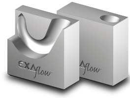
TECHNICAL INFORMATION:
For tunnel gating of medium-to-large sized mouldings.
Supports contouring to a depth of 10 mm. Suitable for gate diameters up to 3.5 mm and shot weights up to 1,200 g per insert.
Available types are GXK-1, GXK-2 and GXK-3.
The Maxiflow from EXAflow® can be used to process all common plastics, including reinforced types (e.g., PA comprising 50% glass fiber).
<< Please check the instructions for the calotte design!

GXK1
GXK2
GXK3
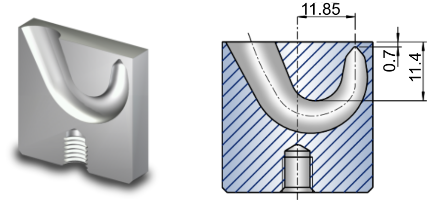
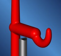
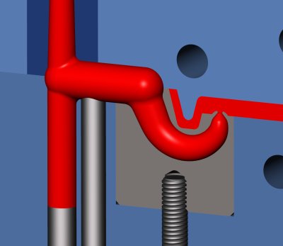
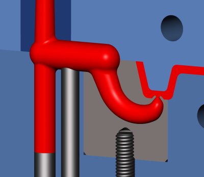
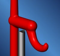
The spherical geometry in the gate area permits gaiting on inclined or curved surfaces.
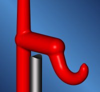
- Maxiflow GXK-1 “Gating point up to 10 mm above the parting line” Features:
- Gating point may be located up to 10 mm above the parting line
- Permits gating immediately behind projecting ribs
- Gate may be remote from moulding wall
- The spherical geometry in the gate area permits gating on inclined or curved surfaces
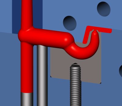
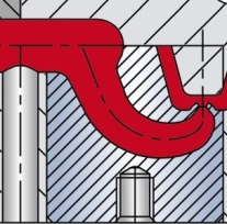
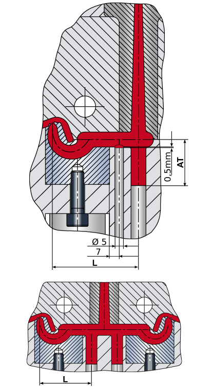
For best operating results the Maxiflow insert requires one central ejector and one supporting ejector. Please ensure that all sharp edges in the runner are thoroughly rounded. For reliable demoulding, the diameter of the runner must exceed that of the curved tunnel.
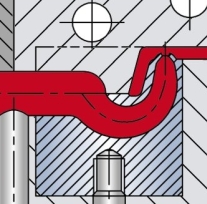
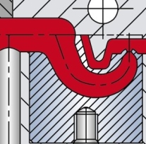
Contouring of a supporting ejector
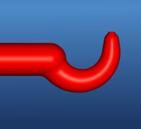
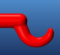
Optimum gate geometry, with edges rounded
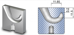
Maxiflow GXK-2 “Gating point up to 5 mm above and below the parting line”
Features:
- Gating point may be located up to 5 mm aboveand below the parting line
- Gate may be remote from moulding wall
- The spherical geometry in the gate area permits gating on inclined or curved surfaces
For best operating results the Maxiflow insert requires one central ejector and one supporting ejector. Please ensure that all sharp edges in the runner are thoroughly rounded. For reliable demoulding, the diameter of the runner must exceed that of the curved tunnel.
Contouring of a supporting ejector
Optimum gate geometry, with edges rounded
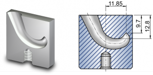
Maxiflow GXK-3 “Gating point up to 10 mm below the parting line”
Features:
- Gating point may be located up to 10 mm below the parting line
- Gate may be remote from moulding wall
- The spherical geometry in the gate area permits gating on inclined or curved surfaces
For best operating results the Maxiflow insert requires one central ejector and one supporting ejector. Please ensure that all sharp edges in the runner are thoroughly rounded. For reliable demoulding, the diameter of the runner must exceed that of the curved tunnel.
Contouring of a supporting ejector

Optimum gate geometry, with edges rounded
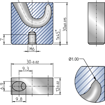
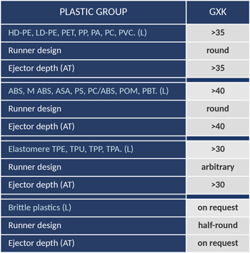
- Installation dimensions “GXK”
Recommended distances “L” from the injection point to the sprue ejector are given below for the various material groups.
The distance “AT” describes the correlated ejector depth.
-
Thermoplastics Elastomers
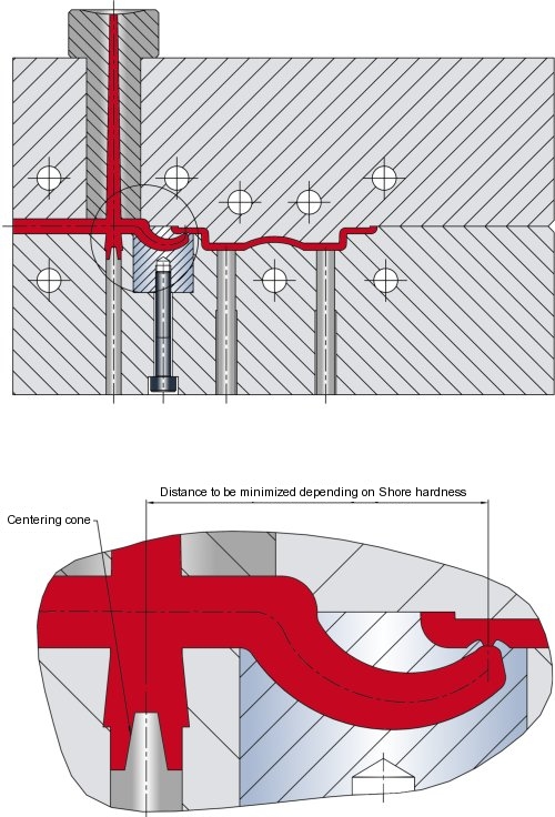
When processing thermoplastic elastomers, please observe the following recommendations to ensure reliable de-molding:
- The distance “L” should decrease with the Shore hardness value.
- The guide length L*0.8 does not apply to TPEs (or TPU, TPA, respectively). In these applications, a centering cone should be provided as shown in our drawing.
- This application instruction applies to elastomers in the medium Shore hardness range (uo to 100 Shore A).
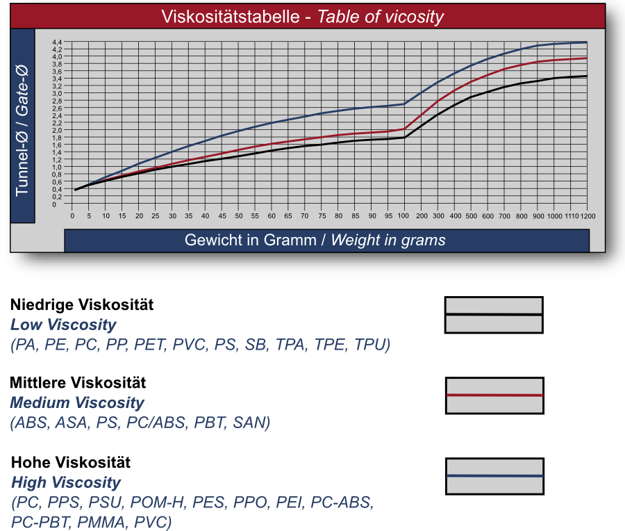
- Gate sizes
We would like to make it as easy as possible for you to select the right gate size. To help you make your choice we have plotted a number of charts indicating the range of possible gate sizes for a given molding weight and material. Please take into account the viscosity of the plastic before making your selection. Since the plastics industry is marketing an ever growing number of modified plastics in each category, it is impossible to provide binding data here. Please also note our warranty disclaimer.
- EXAFLOW Tunnel Gate Inserts
Catamold 420W-DIN 1.4028-X20Cr13 ( until July 2017, 100Cr6 1.3505 )
Material designation:
BASF Catamold 420W – DIN 1.4028 – X20Cr13.
Hardable stainless steel for production of MIM-Parts.Applications:
Components with high hardness and wear resistance combined with good corrosion resistance against water and steam; e. g. tools, cutting blades, surgical instruments, nozzles, bearings.
- High wear resistance
- High corrosion resistance
- Good machinability
- Weldable
Composition:
C = 0.35 – 0.50 %
Cr = 12 – 14 %
Fe = BalanceSurface quality, roughness Ra 0.8 – 1.3
Properties:
Density 7.6 g/cm³ Carbon content 0.35 – 0.50 % Hardness 50 +5 HRC Ultimate Tensile Strength Rm (heat-treated) 1560 mm²