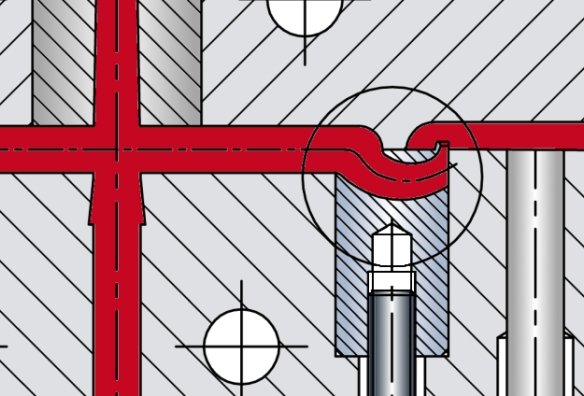
For tunnel gating of small to medium-sized mouldings along a flat parting line.
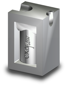
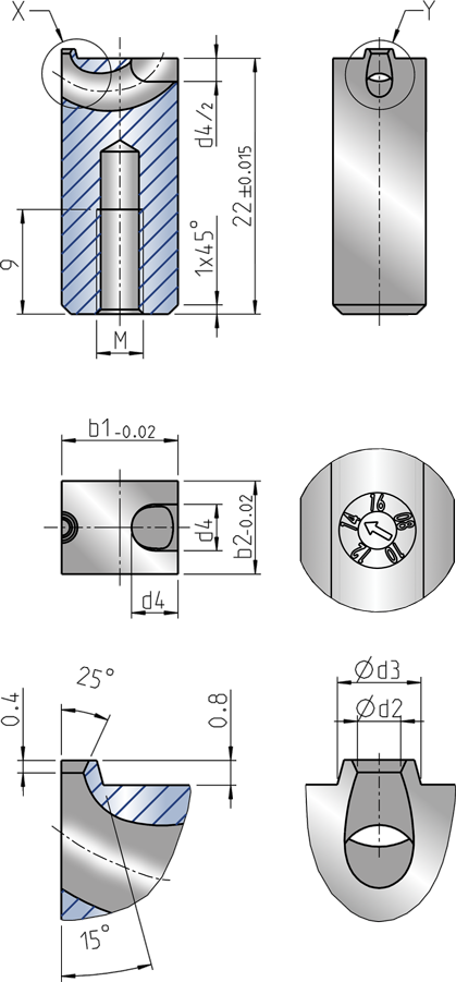
Rectangular design. Available in 10 x 8mm, 12 x 10mm and 14 x 12mm sizes with 0.8 to 2.4 mm gate diameters.
- >> Standardflow “Standard”Features:
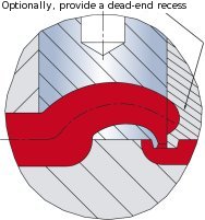
- The front of the gate insert is sealed off by the mould cavity.
- Melt flow exits in vertical direction only, ensuring a clean separation for superior gate point quality
- Optionally, provide a dead-end recess to
- reduce pressure loss.
- avoid jetting.
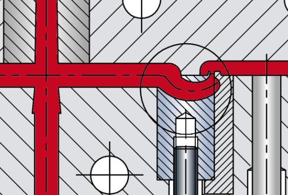
 >> Standardflow “Flat parts” Features:
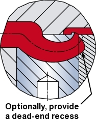
- The front of the gate insert is fully sealed off by a companion calotte (baffle) on the cavity or by an auxiliary insert.
- Melt flow exits in a vertical direction only, ensuring a clean separation for superior gate point quality.
- Optionally, provide a dead-end recess to
- reduce pressure loss.
- minimize shear.
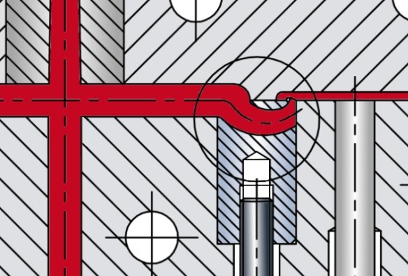
 >> Standardflow “Thin-walled parts” Features:
 - The front of the gate insert is sealed off by the cavity to the level of the parting line.
- Melt flow exits vertically and, to some extent, horizontally.
- Important (in polyolefin applications):
Depending on the plastic used, the gate point will be flush with the bottom surface or may protrude slightly. - Where necessary, provide a companion calotte (baffle) on the cavity or on an auxiliary insert.
- Optionally, provide a dead-end recess to
- reduce pressure loss.
- minimize shear.
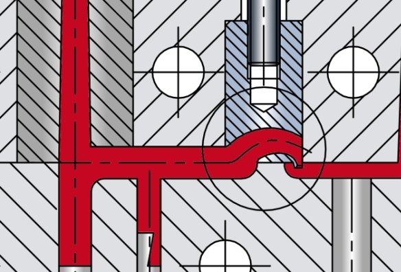
 >> Nozzle-side installation Features:
 - The gate insert is screwed into the nozzle side of the mould.
- The front of the gate insert is sealed off by the cavity.
- Melt flow exits in a vertical direction only, ensuring a clean separation for superior gate point quality.
- The extractor claw must be strong enough to ensure reliable de-gating.
- Use graduated injection profiles to prevent jetting.
- Optionally, provide a dead-end recess to
- reduce pressure loss.
- minimize shear.
- improve frontal flow thus minimizing the risk of jetting effects.
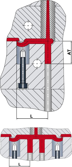
- Installation dimensions “Standard” Recommended distances “L” from the injection point to the sprue ejector are given below for the various material groups. The distance “AT” describes the correlated ejector depth.

- Thermoplastics Elastomers
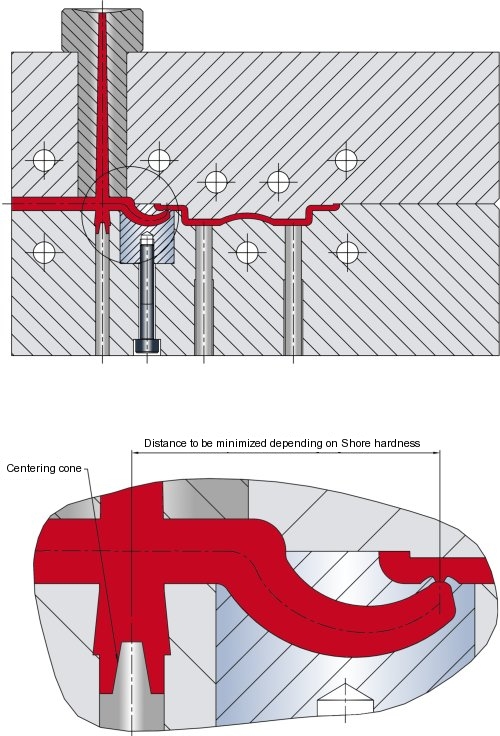
When processing thermoplastic elastomers, please observe the following recommendations to ensure reliable de-molding:
- The distance “L” should decrease with the Shore hardness value.
- The guide length L*0.8 does not apply to TPEs (or TPU, TPA, respectively). In these applications, a centering cone should be provided as shown in our drawing.
- This application instruction applies to elastomers in the medium Shore hardness range (uo to 100 Shore A).
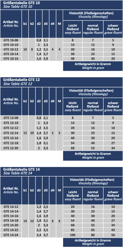
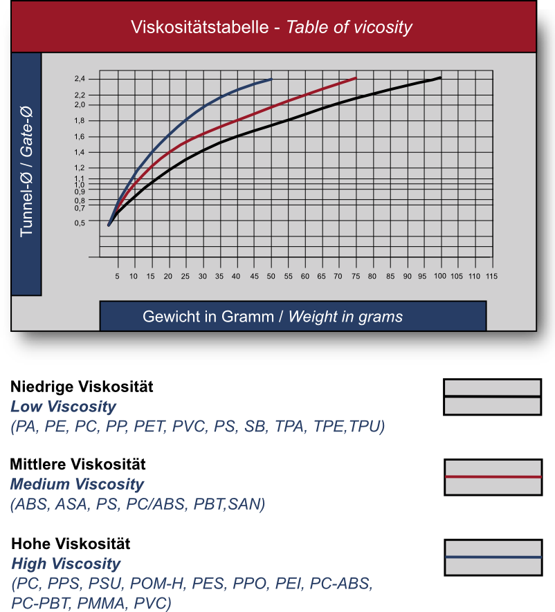
- Gate sizes
We would like to make it as easy as possible for you to select the right gate size. To help you make your choice we have plotted a number of charts indicating the range of possible gate sizes for a given molding weight and material. Please take into account the viscosity of the plastic before making your selection. Since the plastics industry is marketing an ever growing number of modified plastics in each category, it is impossible to provide binding data here. Please also note our warranty disclaimer.
-
EXAFLOW Tunnel Gate Inserts
Material: We have two different types in stock at the moment. To get more details please contact us.
—————————————————————————————————————
Material: 100Cr6 1.3505
Uses: Mechanically moving parts with high wear resistance, high surface hardness, very good cold impact resistance and fatigue strength.
Composition:
C = 0.8 – 1.05 %
Cr = 1,35 – 1,65 %
Fe = Balance
Surface quality, roughness Ra 0.8 – 1.3Properties: Density 7.5 g/cm³ Carbon content 0.8 – 1.05 % Hardness 52 + 3 HRC ——————————————————————————————————————
Catamold 420W-DIN 1.4028-X20Cr13
Material designation:
BASF Catamold 420W – DIN 1.4028 – X20Cr13.
Hardable stainless steel for production of MIM-Parts.Applications:
Components with high hardness and wear resistance combined with good corrosion resistance against water and steam; e. g. tools, cutting blades, surgical instruments, nozzles, bearings.
- High wear resistance
- High corrosion resistance
- Good machinability
- Weldable
Composition:
C = 0.35 – 0.50 %
Cr = 12 – 14 %
Fe = BalanceSurface quality, roughness Ra 0.8 – 1.3
Properties:
Density 7.6 g/cm³ Carbon content 0.35 – 0.50 % Hardness 50 +5 HRC Ultimate Tensile Strength Rm (heat-treated) 1560 mm²